


So since I’m now very interested in keeping everything as stock as possible as far as engine controls goes, I’ve gotten back into researching information on what tools are needed to gain access to the ECU program/flash and decoding the information in it to modify the tune and send it back to the ECU. Known as “chip tuning”.
Of course the sad reality is that in the European automotive world, many things are kept a secret due to greedy tuners and business while other enthusiasts of many Japanese cars get to enjoy the ability to do what we want to do for many years now thanks to many smart people that work together to just make it work. Not to say there isn’t people out there for the Japanese that don’t continue to develop to make money off of it because there is, but in the end there are enough tools (hardware and software) available for you to tune your car yourself on a very acceptable budget.
So, onwards it goes… I’ve been crawling the web to get as much information as possible as to how to tune these ‘pesky’ ECU’s and finding the right tools takes a lot of time (and sometimes money).
I would like to know if anyone else here has been able to gather any information for our ECU’s. I know tuning isn’t for everyone, and while many people ‘want’ to tune themselves, many shouldn’t unless they’re really willing to learn an in depth process.
So far I have found a slew of programs for various VAG cars, some I was able to find for free, others I paid for. Hardware such as KWP2000 cables are obviously something you’ll have to buy but are not going to break the bank.
I’m tired of this all being a secret. Everyone should have the option to tune their own cars for a reasonable amount of money if they choose to put enough work into it. And I’m sure many others feel the same way.
************************************************** **********
So far I have acquired the following programs that seem to be used to edit/find maps and various other things pertaining to VAG cars:
–WinOLS (HEX based map editing that will allow you to display them in various ways, will auto find maps but not tell you what they are. There are files called DAMOS files which are ‘key’ files which contain the info to reveal maps in WinOLS and other tuning software)
–Galletto (allows the reading and writing of flashes/files to and from the ECU using a KWP2000 cable. So yes you can ‘copy’ entire ECU’s this way.)
–VAG EEPROM Programmer (not quite sure yet, seems like this software lets you directly HEX edit the program in the ECU (be it for mileage changes or otherwise related to tuning)
–KWP2000/KWP2000-ME7 (Flashing of KWP2000 protocol ECU’s – ie. Motronic)
–ECM2001 (Tuning of ECU files, checksum correction, plotting of graphs etc. I’ve read that this software is out dated and is not the best to use, but it will allow you to ‘find’ maps and possibly even have something similar to DAMOS files where it already knows and points out what areas of the maps do what)
–ECUFix (allows the correction of checksums of edited flashes so the ECU will accept the files and run them).
….
More ECU tuning tools can be found here: http://www.uobdii.com/wholesale/ecu-chip-tuning/
Programs
Here is a .rar file that has the programs (KWP2000 & TunerPro) and a stock M-box ROM and the M-box .xdf file.
http://www.vaglinks.com/Downloads/S4_tuning.rar
Back up link
S4 tuning.rar – 2.13MB
************************************************** **************-
Basic MAP location information in regards to basic tuning (thanks to Nyet for the info and NorCalS4 for putting it together):
MAP DESCRIPTIONS
FUEL
“Conversion of relative fuel mass (rk) to effective injector on time (te)” – primary fueling
“Desired Lambda for component protection” – requested lambda for component protection when calculated EGT is above “EGT threshold for component protection” (may require a lower “EGT threshold for component protection” if your MAF is not 100% compensated for in “Linearization of MAF voltage”)
“Lambda – driver desired” – requested lambda when calculated EGT is below “EGT threshold for component protection”
BOOST
“Engine load desired” – specified load
“LDR altitude limitation (maximum pressure ratio)” – maximum requested pressure ratio
“Maximum specified load” – maximum specified load
“Maximum specified load IAT correction factor map” – IAT correction for maximum specified load
TIMING
“Ignition angle map”/”Ignition angle map (variant 2)” – primary timing maps. (ME7.1 has a two point variable cam timing system; there is a table for each cam timing state)
MAF
“Linearization of MAF voltage” – compensating for MAF housing diameter (note-sometime when selecting this table in tunerpro, the program crashes)
Bosch Motorsport Technical PDFs!
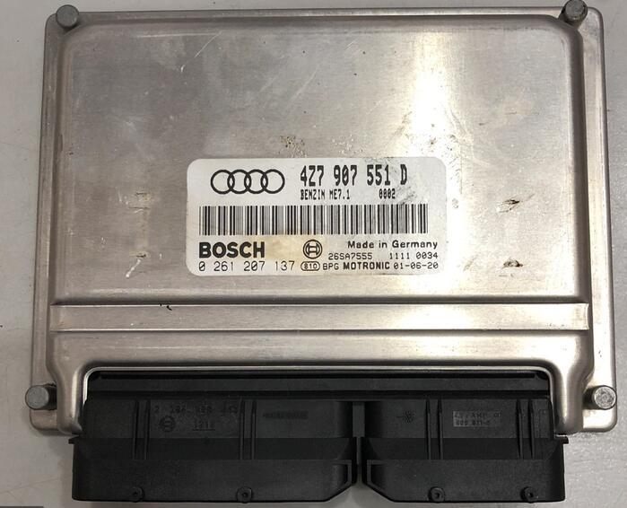
I think I might have just hit the motherload… I came to thinking recently that I remember about a little over a year ago seeing a Bosch Motorsports ECU which looks almost IDENTICAL to the ECU’s found in our cars (and many other newer VAG cars for that matter). So I started digging with google, etc and asking a few people some questions… Well.. Seems like Bosch has recently made the software and documentation for these ECU’s openly available! I doubt the software can be used to tune ‘our’ ECU’s, BUT the documentation itself is worth it’s weight in digital paper 😉
On to the good stuff…
——————————-
Bosch Motorsport:
You can find software on the web
I downloaded the MS 4 Sport Turbo Installation CD which is approx 80MB
It will install everything you need to program the ECU’s along with some very interesting PDF documents! All the code words/short names of ALL the Bosch ECU’s functions. If anyone has read the .XLS files posted in nyet’s webserver (http://nyet.org/cars/files) you’ll notice these ‘short names’ in column A.
I’m going to update more as I fiddle with the software and read some more.
————————————————-
Updated:
New info… So I decided to compare a tuned M-BOX ECU from a big name tuner to a stock M-BOX ECU and here are the following maps that were modified (pump gas tune as car as I can tell). I’m VERY surprised that no timing changes were made which kind of explains as to why my other tuned ECU seems a lot smoother and more aggressive.
PLEASE NOTE: I’m not suggesting that all of these maps NEED to be modified, I’m just listing what I have compared between a tuned ECU and a stock ECU. I have withheld the tuners name due to obvious reasons
MAPS MODIFIED M-BOX vs. STOCK M-BOX ECU:
———————————————-
Engine Load Desired (KFMIRL)
Lambda map at partial load (KFLF)
Max. engine speed on speed signal error detection (automatic?) (NMAXDVG)
Time for LDR overboost active (TLDOBAN) — All zeroed out —
Maximum load at E_ldo LDR (overboost error) (LDORXN) — All set to max 191.25 —
LDR pressure limit at too high engine temp (LDPBN) — All set to max 2550.00 —
rl threshhold for slow LDR-intervention (adaptation) (RLKRLDA) — All set to max 191.25 —
LDR I-regulator limit (FFLDIMX)
Optinal engine torque map (KFMIOP)
Maximum specified load/boost pressure (LDRXN_1_A)
Maximum specified load/boost pressure during knock (LDRXNZK) — All set to 99 —
Max vehicle speed (VAVMX/VMAX)
Max relative indicated torque under open throttle body (RLVMXN) — Set to 181.50 to all bins —
Max relative indicated torque under open throttle body and SU (RLVSMXN) — Set to 181.50 to all bins —
Upper load curve for DKAT active (RLDKTSO_0_A)
Hot start enrichment factor (KFHSTT)
Starting torque (KFMDST_0_A)
Exhaust backpressure correction of the secondary air mass (KFFMSML_0_A)
Characteristic curve for tmot, upper rL control limit for controller before Kat (RLLRTMO)
Characteristic curve for continuous limit value control (fr) (FQTEFR)
Afterstart enrich (FNSA_0_A)
Afterstart enrich (FNSA_1_A)
Constants changed:
———————————————–
Ramp slope during devation regulation of ASR-torque (RAMPASR)
Debounce time for end of cat heater cycles per min during idle (TKHLLAB)
Debounce time for setting of cycle flags (TDDHBKV)
Min. airmass for diagnosis condition (MLWDSLMN)
Wait time for delta-TV diagnosis (DLSA) ready-flag (TWDDTV)
Airmass threshold for dynamic testing behind cat (MLLASH)
Tank ventilation time for basic adaption (TTEGA)
Pressure gradient factor during evacuation of the brake booster via electrical pump (DPBKVEVKEP)
Factor for calculating min. pump pressure dependent on ambient pressure (FBKVP)
Maximum engine speed on speed signal error detection (NMAXDV) — Set to MAX engine speed —
Maximum airflow for load calculation following SAE J1979 (MLMAX)
Supplemental codeword: short strip requirements display group 195 (CWFA195A)
————————————————–
M-Box Map definitions somewhat translated by NOTORIOUS VR:
Originally Posted by the dog
Inverses Pedalkennfeld für FGR-Betrieb (KFWPFGR) 12×16 (%) – Inverse Pedal recognition for FGR??-Activation
Kennfeld normierter Massenstrom über DK (KFMSNWDK) 6×16 (has km/hour and % )
Lambdakennfeld bei Teillast (KFLF) 12×16 (%) – Lambda values by half throttle
Kennfeld für Drosselklappen-Sollwinkel (KFWDKMSN) 6×16 (has km/hour and % ) – Values for Throttle body angle target
Kennfeld Meßfensteranfang Klopfregelung (KFMAKR) 4×16 (%)
vorgesteuerter Dynamikvorhalt (KFDYMNT) 8×16 (C)
Lastdynamikerkennungsschwelle (KFDYES) 6×16 (%) – Dynamic Load recognition threshold
Dynamikvorhalt Erkennungsschwelle (KFDYRS) 6×16 (%)
Dynamikvorhalt Offsetschwelle (KFDYRSOF) 6×16
Klopferkennungsfaktorkennfeld Zündung 1 (KFKEF1) 3×16 (%)
Klopferkennungsfaktorkennfeld Zündung 2 (KFKEF1) 3×16 (%)
Klopferkennungsfaktorkennfeld Zündung 3 (KFKEF1) 3×16 (%)
Klopferkennungsfaktorkennfeld Zündung 4 (KFKEF1) 3×16 (%)
Klopferkennungsfaktorkennfeld Zündung 5 (KFKEF1) 3×16 (%)
Klopferkennungsfaktorkennfeld Zündung 6 (KFKEF1) 3×16 (%)
Klopferkennungsfaktorkennfeld Zündung 7 (KFKEF1) 3×16 (%)
Klopferkennungsfaktorkennfeld Zündung 8 (KFKEF1) 3×16 (%)
Faktor Delta Lambdasoll für Bauteileschutz (KFFDLBTS) 16×12 (%)
Lambdasoll für Bauteileschutz (KFLBTS) 16×12 (%)
Kennfeld LDR I-Reglerbegrenzung (KFLDIMX) 8×16 (hPa) – Field for Boost Pressure Adjustment (intergral??)-limit
KF zur Linearisierung Ladedruck=f(TV) (KFLDRL) 10×16 (%) – Field for Linarization of Boost Pressure=f(TV)
LDR-Regelparameter Q0 (KFLDRQ0) 4×16 (hPa) – Boost pressure adjustment parameters Q0
LDR-Reglerparameter Q1 (Integratorbeiwert) (KFLDRQ1) 4×16 (hPa) – Boost pressure adjustment parameterers Q1 (Intergral values)
Kennfeld LDR-Reglerparameter Q2 (KFLDRQ2) 4×16 (hPa) – Boost pressure adjustment parameters Q2
Schwelle für dynamische Schubumluftventilsteuerung aktiv (KFSDLDSUA) 16×6 (hPa) – Threshold for dynamic Bypass Valve Control? active
optimaler Zündwinkel (KFZWOP) 11×16 (%) – Optimal Ignition Angle
optimaler Zündwinkel Variante 2 (KFZWOP2) 11×16 (%) – Optimal Ignition Angle Variant 2
Kennfeld optimales Motormoment (KFMIOP)11×16 (%)
Offset des optimalen ZW bei AGR-Betrieb (KFDZWOAGR)11×16 (%) – Offset of optimal Ignition Angle when AGR??- is active/runing
Relatives Fahrerwunschmoment aus Fahrpedal (KFPED) 12×16 (% PED) – Relative Driverswish from Pedal
Relatives Fahrerwunschmoment aus Fahrpedal für kleine Geschwindigkeiten (KFPEDL) 12×16 (% PED) – Relative Driverswish from Pedal for low speed
Relatives Fahrerwunschmoment aus Fahrpedal für Rückwärtsgang (KFPEDR) 12×16 (% PED) – Relative Driverswish from Pedal for in reverse gear
Kennfeld für Berechnung Sollfüllung (KFMIRL) 16×16 (%) – Calculation of Target filling?
Kennfeld optimales Motormoment (KFMIOP) 11×16 (%) –
Schleppmoment Drehzahl- und Lastabhängigkeit (KFMDS) 11×16 (%) – Engine speed drag moment and load dependancy
Kennfeld für Nockenwellenspreizung bei Katheizen (Einlaß) (KFNWKHE) 8×16 (kw %)
Sollwinkel Nockenwelle bei klopfender Verbrennung Einlaß (KFNWKRE) 8×16 (kw %)
Kennfeld für Nockenwellenspreizung (Einlaß) (KFNWSE) 8×16 (kw %)
Kennfeld für Nockenwellenspreizung im Warmlauf (Einlaß) (KFNWWLE) 8×16 (kw %)
Korrekturfaktor Kraftstoffversorgungssystem (FKKVS) 16×16 (ms (up to 19… injectors…????) – Correctionfactor of fuel supply system
Schließzeitkorrektur in Abhängigkeit von UB (KFSZDUB) (no rpm ….V vs ms)
Zündwinkelkennfeld (KFZW) 12×16 (grad KW %) – Ignition advance lookup field
Zündwinkelkennfeld Variante 2 (KFZW2)12×16 (grad KW %) – Ignition advance lookup field Variant 2
delta Zündwinkel bei Dauerklopfen (KFDZK)12×16 (grad KW %) – delta of Ignition angle by constant Knock
Schwelle der ZW-Spätverstellungen für ZW-Kennfeldumschaltung (KFSWKFZK)12×16 (grad KW %)
Kennfeld mit dauerhaft spätest möglichem Zündwinkel (KFZWMS)12×16 (grad KW %)
Min-Zündwinkel (KFZWMN)12×16 (grad KW %) – Minimum Ignition Angle
Min-Zündwinkel Katheizen (KFZWMNKH)12×16 (grad KW %) – Minimum Ignition Angle by Catalytic heating
Min-Zündwinkel für Start und Nachstart (KFZWMNST)12×16 (grad KW %) – Minimum Ignition Angle for Start and Afterstart
HOW-TO BENCH FLASH Audi S4 ECU USING GALLETTO
The basics of what you NEED to know:
**************************************************
1.Use Galletto when possible, it allows you to flash in boot mode (when on the bench) and is MUCH faster then the regular old OBD KWP2000 protocol in slow mode. I have only used Galletto so far and it’s always worked for me!
2.Bench flash your ECU with a good DC power supply set to 13.5V! Don’t even bother to flash in your car under it’s own battery power. If you have to flash in the car at least connect a batter charger!
3.MAKE SURE YOU MAKE A BACKUP OF YOUR ECU FIRST! YOU WANT TO BE ABLE TO GO BACK TO A RUNNING ECU IF SOMETHING GOES WRONG!!!
With that out of the way, reading and writing to the ECU is pretty simple and everything I explain here will assume you’re bench flashing.
1.With the ECU open and on the bench connected to your bench flash harness make sure the power supply is on, but the ignition switch is off (or whatever you use to simulate the ignition switch), connect your KWP2000 cable to the OBD port and start Galletto.
2.You now need to touch PIN 24 on the flash chip (800BB) to ground before turning on your switch/ignition signal. PIN 24 the the 2nd one in from the left side on the bottom. The chip when you’re looking at it should have a circle in the top right hand corner (indicating PIN 1). Also the ECU’s plugs will be facing to the RIGHT! Once you touch PIN 24 to ground, turn on the ignition switch and remove the ground from PIN 24 about 2-3 seconds later. You are now in BOOT MODE.
3.In Galletto, select Audi from the top drop down box (MAKER), and then scroll all the way down to the bottom of the next drop down (DRIVER) to the BOOT MODE section where you will find two choices. You’ll probably want the 800BB flash selection (if in doubt verify what it says on the flash chip).
4.Click on the ECU Data button and allow it to complete, you should see some numbers appear in the top left box (sometimes you also see the words: “ECU NUMBER NOT FOUND” which seems to be ok too so don’t worry if you see that).
To “read” the ECU and save a .bin to your computer click on the Read ECU button (this is where you can backup your ECU just in case! So do it NOW!), to write a .bin file to your ECU (either tuned or stock) click on Open File then select the .bin file you want to program into the ECU and then click on Download File.
One quick thing about this… Once you put the ECU in BOOT MODE, any time you remove power or turn off the ignition switch you will need to apply ground to PIN 24 again just before turning the ECU on again to do any functions in Galletto on the bench. I have also found that even though Galletto Fgtech asks you to turn on/off the ECU during certain operations (IE. when you click on ECU Data and then want to write a file using Download File you DO NOT have to turn the ECU off and then on again. It works just fine leaving it on as long as you haven’t done a read/write procedure yet (or either Read ECU or Download File buttons).
(Many many many thanks to NOTORIOUS VR)
