


Not my work but little contribution. How much you can see KTAG use for 2 pins +12V power supply pins connected via V-KEY, the same pins-wires you have and in KTM bench cable. Will work like this, I do not know, or must be connected all 3 pins to permanently +12V.
You need to connect boot and cnf1
pcmflash module 53
this ecu not support GPT pins
Minimum power of 13V. I use 14V in this ecu or it does not work.
Yes very power hungry ecu i use 14.5v 15A.
I recently worked out how to make this work using PCM flash.
My instructions here:
I have got it working using a combination of 3 different pinouts and it works good, no resistors are needed.
Just so that people know, here are instructions for future use:
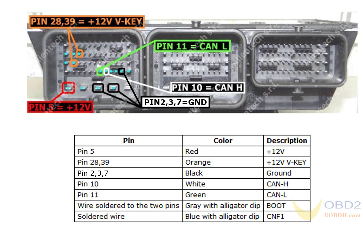
1. For the pinout to the ECU connector, combine both pinouts, so you have 3 +12v (pin 5, 28, 39) and 3 x GND (pin 2, 3, 7)
then can Hi (10) and Lo(11).
2. No resistors are required.
3. Connect CNF1 (blue wire) as shown on the diagram above (see KTAG pinout for boot pins).
4. Connect 2 x boot pin (grey wire) as shown above.
5. Go to module 53, scroll down to read password PSA SID208.
6. Save password.
7. To read/write ECU, connect using TC1797 and load the password file, change the setting from automatic to the saved password file.
It works really well, and I definitely didn’t need to solder any resistors.
Trying to read…
– not connect
– not connect
– Go to module 53, scroll down to read password PSA SID208 –> = 1.
Save password –> = 2.

Skoda Super B 2.0 TDI EDC17CP14 read/write OK. Read after write, compare files, checksum repaired.
Credits to @ credoline
Learn more:https://www.uobdii.com/wholesale/ktm-bench-ecu-programmer.html
