Here is all i did with my G7 Honda Accord
I started my final attempt to separate the Audio-Radio unit from the combined LCD display HVAC board (full Climate control system) in G7 Honda Accord.I have decided to post the updated design, circuits and info on the install here, this forum is more technically orientated towards circuit and microprocessor design along with Car-PC integration and it may be of more interest to a few in this forum. This is an unfinished project, but its getting close.At this point it’s taken some time using the system to reach a final hardware – software design that not only covers everything I want now, but is also expandable to cover future ideas and needs. I have redesigned the hardware interfaces and designed a separate microprocessor unit for general vehicle IO interface.
After using the system with my basic $25 “Push Button-Rotary encoder” and reading up on BMW’s iDrive hardware-software control system, I have decided that this has a lot of merit in any vehicle application. I redesigned the hardware interface to allow for this and much more in the future.
New hardware has been installed and I have spent a lot of time drawing and documenting all circuits and connections. The complexity designing hardware interfaces, programming microprocessors and writing software for the Frontend Windows application is enormous – especially with a fully integrated control system with Climate control and vehicle systems hardware and PC interface.
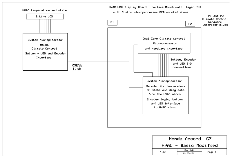
I have finalised the circuit and layout for a simple standalone system. It allows you to remove the Accord Audio system and to interface and relocate the Climate control PCB. This allows full manual control of the HVAC with a small LCD display for HVAC temperatures and status. – NO PC needed
The system can be scaled up to full PC control and vehicle interface, which is the main focus of this thread.
Some circuits and layout follow.
History:
No one (apart from rumours) has successfully removed the combined “Dual zone climate control and LCD Radio 6 CD stacker unit” AND retained a fully functional climate control system. This last point is important.
Single zone (non climate control) systems have been removed with aftermarket kits. These basic systems leave a lot to be desired and work with of the shelf audio units. Basically a simple manual control of the basic single zone AIR-CON and a blank panel are supplied.
Dual zone “full climate control” systems are a complex system in any vehicle and unless the system has been reversed engineered correctly it performs poorly or not at all. Many owners who purchased replacement aftermarket integrated NAV-Audio solutions from China supposedly made for the Honda Accord G7 have found this out the hard way.
The problem is twofold.
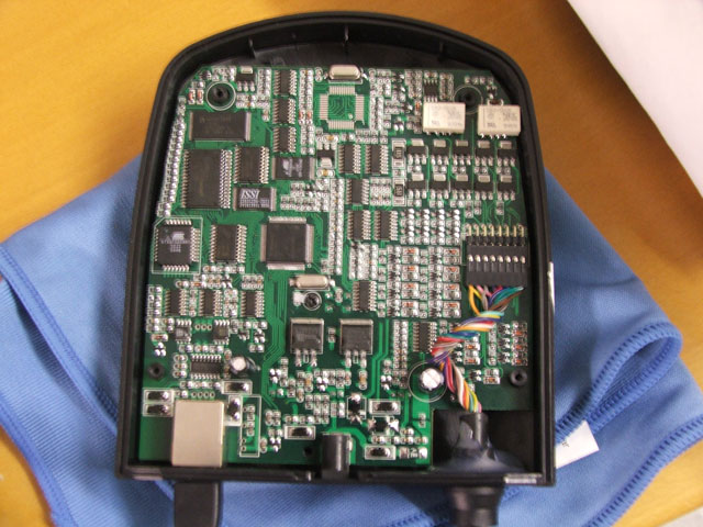
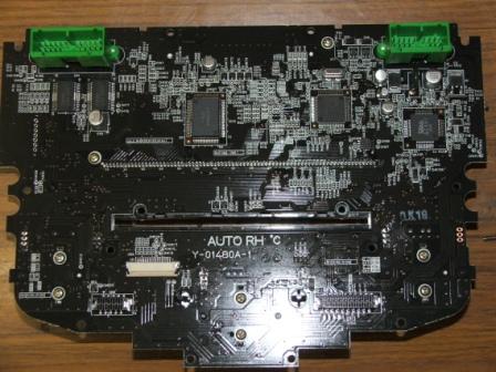
1. The LCD display is made up of a number of fixed graphic display sections. A few are for HVAC temperature display and operational status. The rest display 6 CD stacker, AM-FM and Audio system information. The LCD module has over 75 connections to the PCB. Most people crack or shatter the module if they try to remove it without damaging the board.
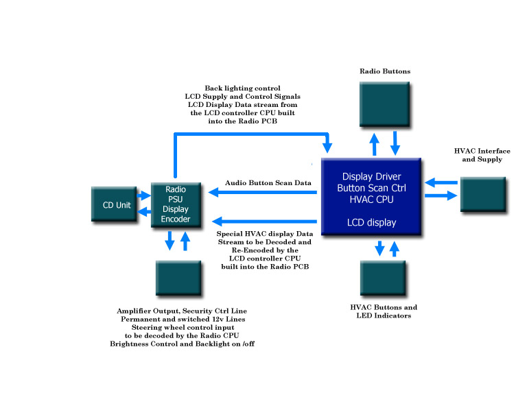
The Audio – 6 CD unit mounts behind the front panel display PCB – This is a very large multi layer surface mount design board, size is 7” x 10” and almost as big as the front panel. It incorporates a large fixed segment LCD with all radio buttons, audio controls, LCD interface, key scan controller, HVAC buttons and HVAC microprocessor Climate control systems spread around the PCB.
2. The LCD display and front panel were designed primarily as a split part of the Radio-Audio system. The microprocessor interface that drives display data, power supply and control of backlighting and control illumination and all data clocking/strobe signals are coded inside the Radio-Audio unit.
The unit was obviously modified to take an undocumented single wire data stream (it took some finding) from the HVAC microprocessor and display it via the decoded/encode function in the radio.
There are no circuits (that I have been able to find) for the HVAC-LCD PCB or Radio – Audio microprocessor systems.
Removing the Radio-Audio system from the front PCB leaves you with nothing except a functional but blind Climate control system; and a very large PCB that had to be relocated if you want to use the space occupied by the removed Audio system. Doing so means that you no longer have any buttons or controls for the HVAC system as they are surface mounted on the main PCB behind the front panel.
Microcontrollers to the rescue.
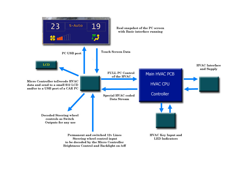
Here is my journey to removing the existing system, fitting a CAR-PC and making the Climate control system fully touch screen integrated while retaining manual control for ease of use and for times when the PC or screen fails or are turned off.
Note: By integrated, I mean as good as or better than OEM in ease of use, response and feedback (display).
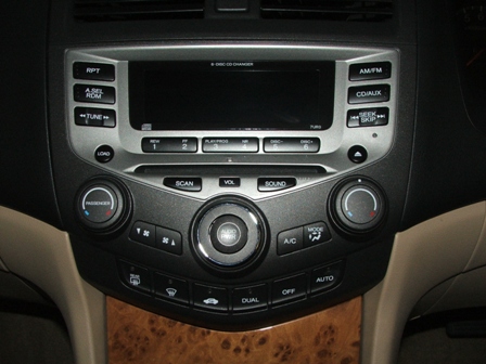
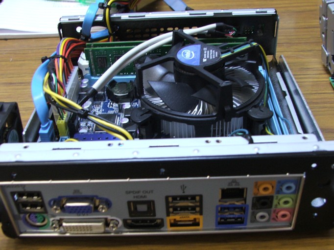
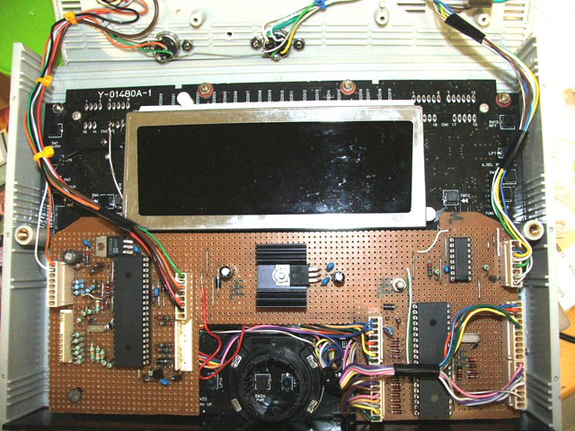
The existing unit.
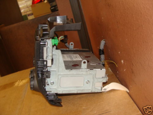
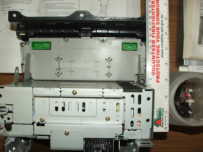
Radio unplugged from the front panel.
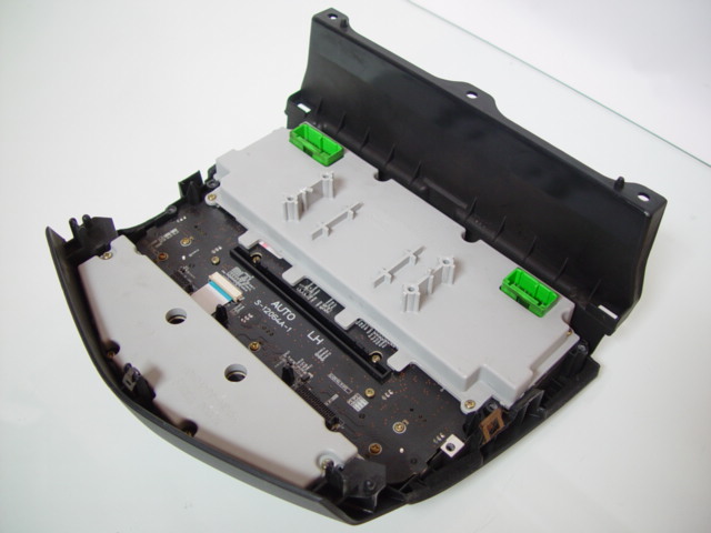
Main HVAC-LCD PCB
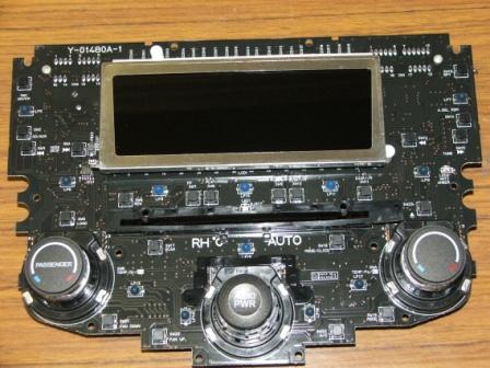

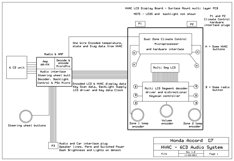
Here is the original layout in two formats.
Using a digital storage CRO I managed to identify a repeating data stream on an HVAC control line. Once all timing information had been calculated I set about programming a Microcontroller to decode this stream and send raw data to a USB port on the PC. I had the task of decoding the raw data and identifying which functions each bit in the stream controlled or indicated. This has been accomplished and the picture shown is an actual screen capture of the basic display software I wrote running on the PC. – This has not had HVAC controls added at this time – just the temperature display.
And the basic modified proposed layout.
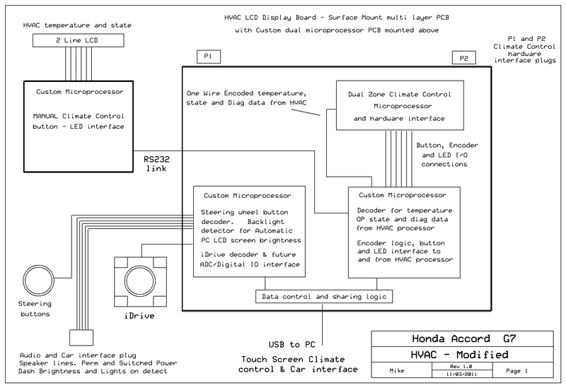
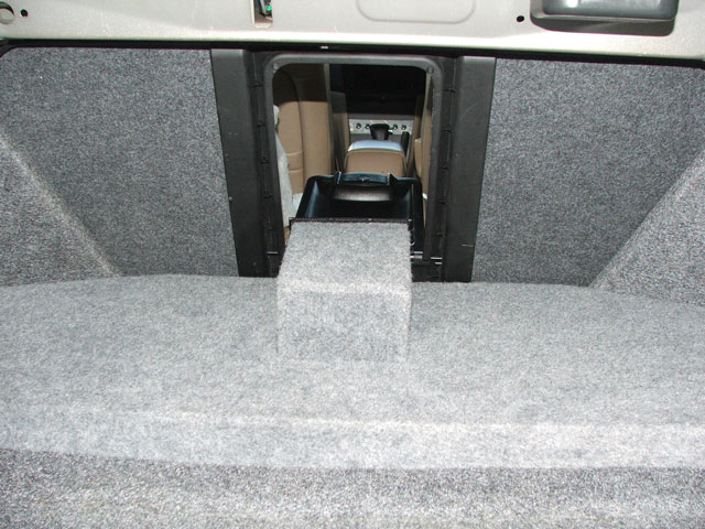
The Display-HVAC PCB (7” x 10”) will not fit back into the console if it spaced back even slightly. Honda made this board to just fit in the opening and the opening get smaller with depth.
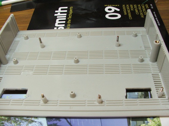
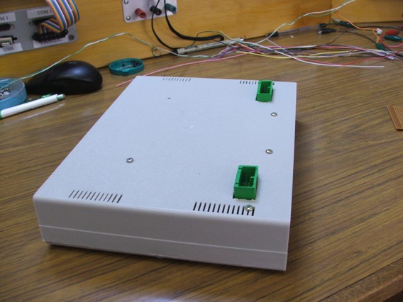
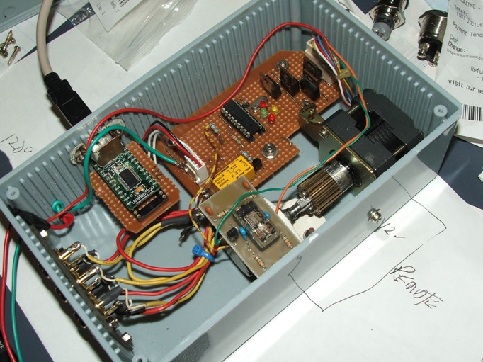
This forced me find a case and a location to mount it. I used an “off the shelf” plastic electronic case that is low cost and almost a perfect fit for the PCB.
The picture shows the new case with existing HVAC sockets protruding through bottom, just as the OEM unit did.
The prototype PCB mounded in the case above the relocated HVAC-LCD PCB.
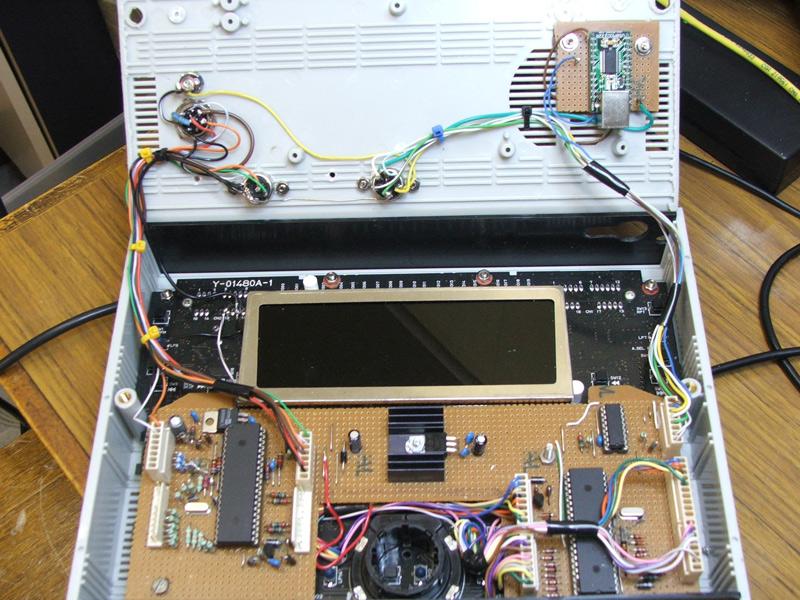
This includes sockets for the RS232 link to the Manual control Micro. The Car systems and USB interface.
The “false” or “backing” fascia. The only item attached to this is the 8” touch screen and soon to be added Remote Manual Climate control buttons with small Microprocessor interface.
A padded panel covered to match the trim will clip onto this backing panel and follows the curves of the dash down to the centre console.
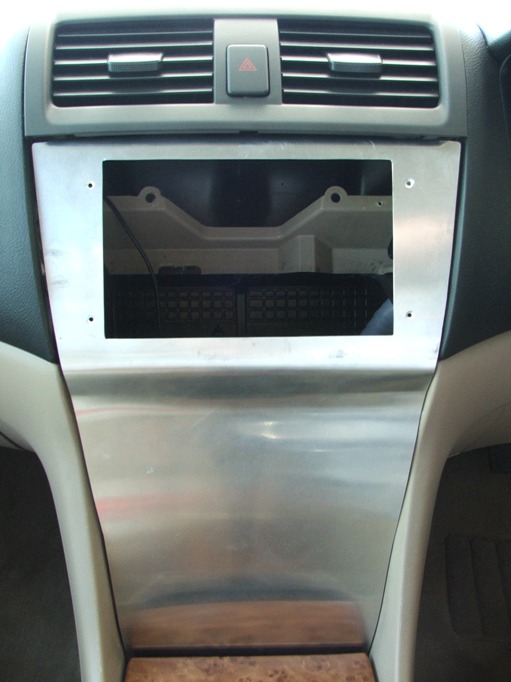
The backing panel mounts via the same three screw locations that held the OEM Audio/display unit into the top of the dash. The bottom is secured using two screw mounts that held the cubby in place.
I have incorporated the same holding mechanism as the OEM Audio unit utilised to lock the top vent panel into the fascia.
The backing facia is removed in the same fashion as the OEM unit. IE. Remove the top vent panel, remove the ashtray – or whatever they call it – remove the three top screws and the two lower screws and your done.
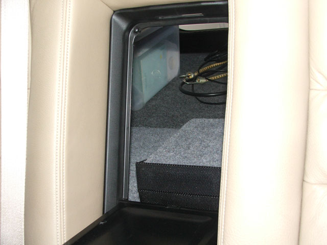
The Ashtray houses a number of USB sockets accessible when the lid is open.
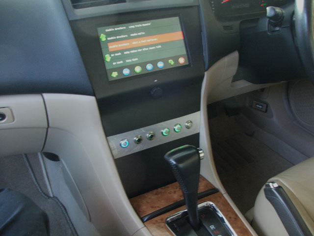
This is a picture of the screen installed “roughly” just to get an idea of the usability of the HVAC when driving – It’s so nice to use.
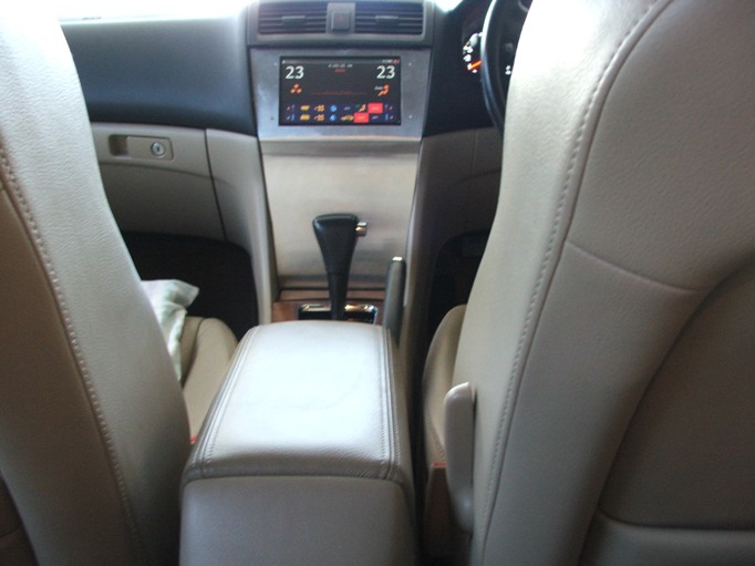
The highlighted buttons indicate what functions are running in the same way as the OEM unit lit LEDS for Auto, Demist, Recirculate, etc. These screen buttons are lit by commands from the HVAC itself. I convert the existing LED signals on the HVAC PCB into data commands and incorporate them into the original HVAC coded data packets coming back to the PC.
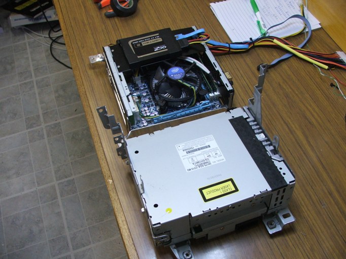
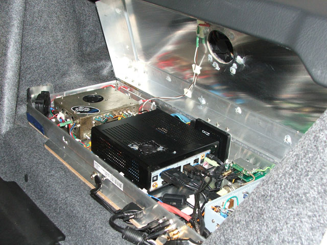
The PC is mounted in a Mini-Box metal case.
Size comparison to the old Radio-CD unit.
Screen: CTF800-WMSL – VGA 8.0″ (16:9) TFT – Touchscreen USB
OPEN-FRAME (500 nits, LED backlight) -TRANSFLECTIVE PRO – Sunlight viewable.
Operating system: Windows7.
Load time: 11 seconds.
Shutdown time: 2 seconds.
Bios Initialisation time 15 seconds.
Standby to on time: 2 seconds.
Standby current: 240mA.
Motherboard: GA-H55N-USB3 5.5” x 5.5”
Support for an Intel® Core™ i7 series processor/Intel® Core™ i5 series processor/ Intel® Core™ i3 series processor in the LGA1156 package
1. 2 x 1.5V DDR3 DIMM sockets supporting up to 8 GB of system
2. Dual channel memory architecture
3. Support for DDR3 1666 (O.C.)/1333/1066/800 MHz memory modules
4. Support for non-ECC memory modules
5. Support for Extreme Memory Profile (XMP) memory modules
6. 4 x SATA 3Gb/s connectors supporting up to 4 SATA 3Gb/s devices
1 x eSATA 3Gb/s connector on the back panel supporting up to 1 SATA 3Gb/s device
Up to 8 USB 2.0/1.1 ports (4 on the back panel, 4 via the USB brackets connected to the internal USB headers)
Up to 2 USB 3.0/2.0 ports on the back panel
Processor: Intel i3 540 @ 3GHZ
RAM: 4 GB
Hard Drive: Solid State – OCZ 50GB.
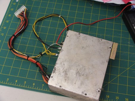
Power Supply: M4-ATX, 6v to 30v input. 250 Watts – 300 Watts peak, fully Programmable.
The power/current drain when playing a movie is 36 to 48 watts – 3A to 4A.
GPS sensitivity and DAB-FM reception
I ran into trouble with GPS sensitivity and DAB-FM reception. A search of CAR-PC forums revealed this to be a common problem and with users searching for an answer. The main problem is 12V ATX power supplies that need to provide full ATX output voltages when down to 6 volts input during cranking.
Because of the nature of GPS and the signal levels involved, any digital noise will desensitise or block GPS reception.
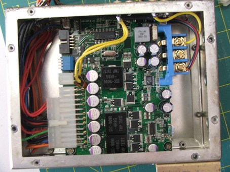
I came up with a solution which I have shared with others in the Power supply section. This involves installing the Power Supply (PSU) in a copper or aluminium case and filtering every input/output lead via a feed through capacitors.
This was the test setup with long leads. It worked and is now rewired and fitted in a case in the boot with the MB.
The second concession I had to make was to remove the PC from the dash and install it in the boot of the car. Noise from the PC was still enough to block GPS as the GPS receiver that comes with Garmin Mobile PC has no external aerial connection and besides, I wanted to fit this tiny receiver underneath the centre dash panel at the base of the front windscreen – Just behind the sunlight sensor for a no visible GPS installation.
After carrying out both mods the GPS has full satellite reception with the car sitting in the almost enclosed metal carport. FM reception from the rear glass mounted aerial shows no interference from the CAR-PC and PSU that are mounted a short distance away.
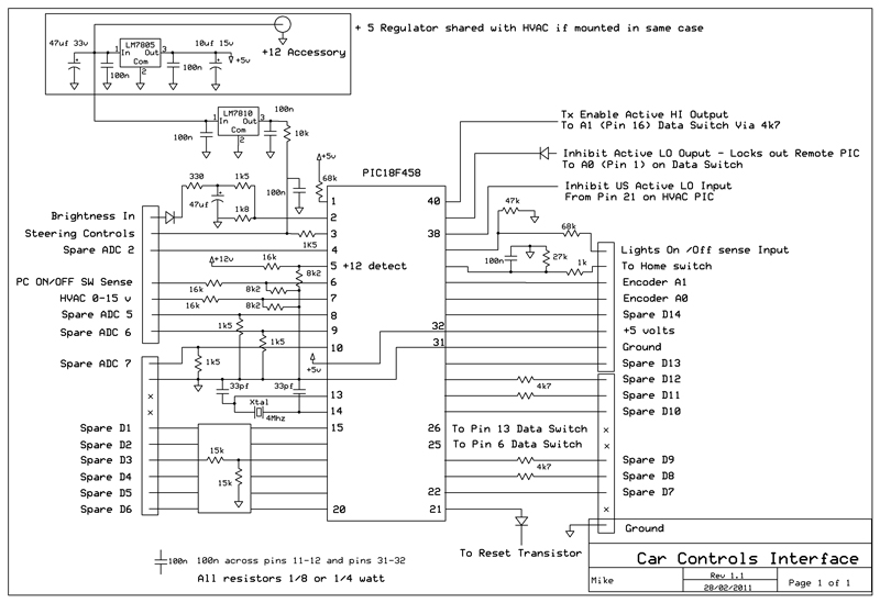
Circuits.
Basic connections for a standalone (NO PC) installation.
Modified system with CarPC interface and Vehicle system interface micro.
Overall block layout of the system in the vehicle.
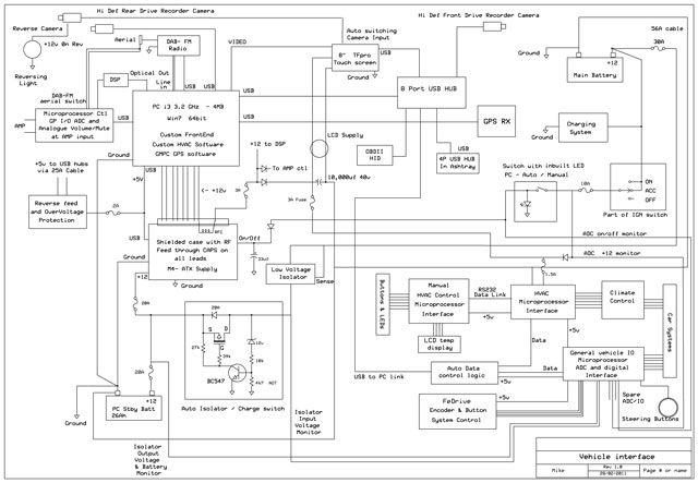
A high res version than can be zoomed.interface
Connections between the 2 microprocessors mounted with the existing HVAC PCB and the Manual remote HVAC controls micro.
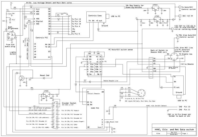
Remote Microprocessor.
HVAC Microprocessor.
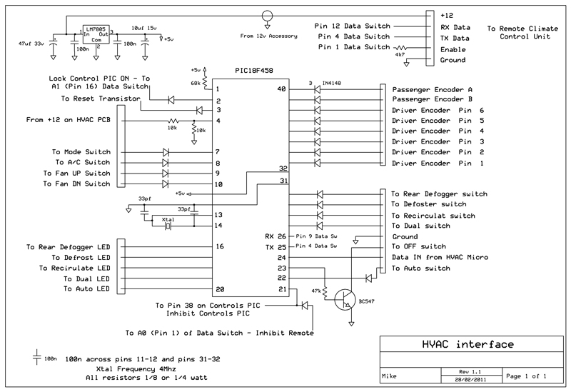
Vehicle interface Microprocessor.
Frontend software.
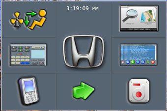
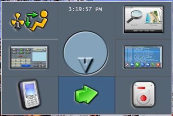
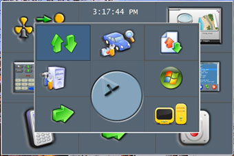
Main Menu. Pushing the Rotary encoder button (soon to be iDrive) brings this screen up from anywhere, including if you exited to the operating system.
Because this system is fully controlled by the car controls and iDrive system, there is no need for navigation buttons taking up precious screen space when GPS, Radio, Audio screens etc are displayed.
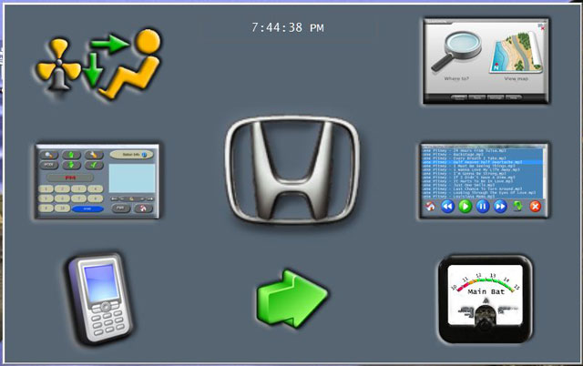
The Big white/red button allows you to shut the PC down (after conformation) instead of having it automatically go to suspend to RAM mode when the vehicle is switched off.
UPDATE: Big white/red button removed and now made Automatic with the Hardware Auto/Manual button – see page 4
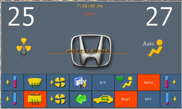
Climate Control. This is a full two-way transfer system with Highlighted buttons reading and reflecting the LED ports on the existing HVAC microprocessor. When a button is pressed, the on-screen button state and display only change when the HVAC responds with the new state. The system response time is virtually instant.
The Mode button on the steering wheel cycles through the main 4 applications (if they are running) and announces each application in turn. When the Climate control is displayed the volume UP/DN buttons change and announce the passenger temperature, the Channel UP/DN buttons do the Driver temperature.
———- Post added at 03:59 PM ———- Previous post was at 03:54 PM ———-Menu2. Deals with non-essential programs and information not used when driving.

Setup Screens.

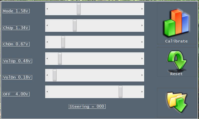
Steering Button calibration. I have manual OR fully automatic options to setup the voltage switching levels in this system. This allows for experimenting and expanding the system down the track
update:
there are a few units available on line that tap into the Can bus for door/key entry, alarm and a few other functions from the Body control module. I have no need for this so far. However that will change when I integrate a wireless alert module into the system a little down the track.
For other interfaces to voltage and sensor systems in the car I find it easier and faster to tap the required sensors back to the micro. Just me I guess.
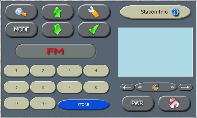
DAB-FM radio.
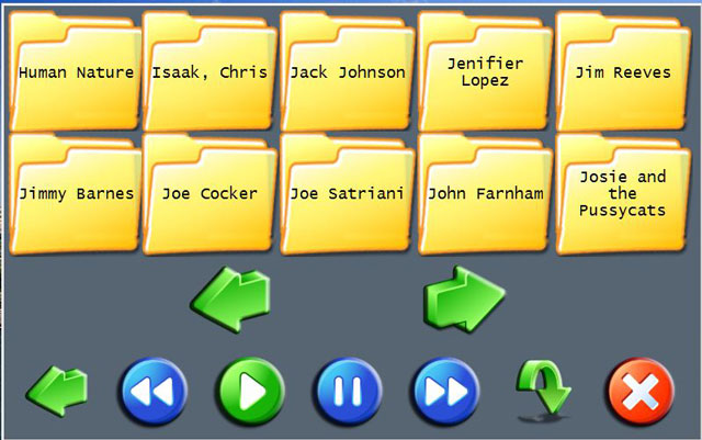
Audio player setup and player screens.

Screen position and non full screen size. All external applications such as GPS are automatically resized and moved to fit the Frontend size and position.
The Frontend normally runs in full screen mode, this setup allows me to move it to a different monitor. Double clicking the Time display on the Main menu toggles between full-screen and a preset size set here. Fonts are adjusted automatically with screen size however the adjusting point can be changed to suite.
The Screen brightness can be manually set to automatically darken to a preset level when the Car Lights are turned on. OR it can be set to automatically read and track the Dash lights brightness level.
Dash light fine tune for level tracking is also adjusted here.
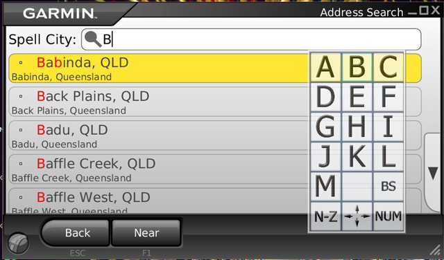
Garmin Mobile PC GPS
With my OSK:
Background: Garmin Mobile PC GPS software does NOT come with an on screen keyboard (OSK) and most OSK’s I have seen duplicate a standard Keyboard which is just ridiculous for GPS navigation input use. So, once again I wrote my own. Nice thing about this is it does not obscure the screen and is opened or closed by touching the “GARMIN” text at the top left of the screen.
It works as well as a standalone Garmin GPS I gave to my wife. I also have the GPS map zoom in or out with the CH-UP and CH-DN buttons on the steering wheel when the GPS is on screen.
Garmin GPS can hang – see forums – To this end I have included code to detect if the GPS window is lost. Any remaining task is automatically killed, the GPS USB RX is issued with a hardware reset, the GPS application is automatically restarted and the commands issued to bring it to the MAP display screen. Takes about 3 seconds. The GPS is also automatically started and set to map display from a cold boot.
External applications setup. All fields can be filled in automatically or edited.
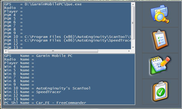
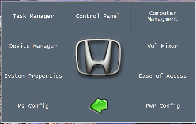
Window applications setup.
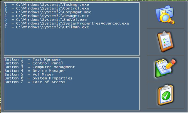
The Window app menu. Great when needed quickly during setup of new hardware or software.
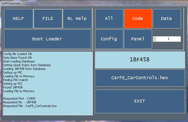
Program Firmware.
I wrote a boot-loader into the firmware when I designed the code for the micros. This window allows me to update firmware in a few seconds. The Processor to be programmed is locked onto the data-steering switch by the other processors, these inturn go into a halt state. This ensures the correct processor is programmed and no data flows unexpectedly from any source. Automatic resets are sent when the operation is finished. About 4 seconds from the press of the button.
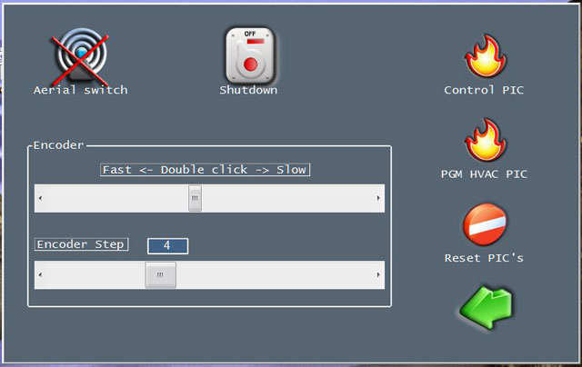
Automatic aerial changeover between DAB and FM aerials is also set here.
FEiDrive Encoder options and Menu clicks are set here as well.
Boot-loader screen without the Progress bar showing.
Vehicle diagnostics/monitoring.
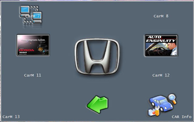
This window allows me to run quite a few external applications for Vehicle diagnostics. I have a Honda factory hardware interface module and the Honda factory software that runs with it. Also have Auto Enginuity OBDII interface software with USB module. The last menu accesses the current Sensor inputs from the Control/vehicle interface micro. I’m still finalising this screen so excuse strange text.
Right from the start I realised that a manual volume control was needed. This is a prototype with a small micro to turn an analogue volume control via a small stepper motor.
A new unit in on the way; both include ADC inputs for monitoring the charge current and voltage of the PC battery mounted in the boot. Other controls include outputs for automatic DAB-FM aerial switching and Audio inputs selections that bypass the PC audio but still operate seamlessly from the Car-PC and iDrive, of course a hardware mute the halts all sound until the Front-end is loaded and the un-mute command is given is included.
Some of the problems with a CarPC solution.
I have spent the past five months designing hardware and writing software/firmware, trying to make a carpc running Win7 64bit feel like an OEM installation. Im getting close!
From this perspective here is my take on some of the problems encountered.
Software from manufactures, in particular GPS, is so full of bugs that I feel they breach the fit for intended purpose laws. I use Garmin MPC (now discontinued but still updatable as it uses standard Garmin maps), I had to write an OSK and code the Frontend to detect when GMPC hangs. The code performs a transparent kill of the GMPC task and hardware reset of the USB RX device followed by an automatic reload and initialisation of the GPS software. I like the Garmin PC software, it looks and performs exactly like my 4 Garmin Car GPS and it looks great on an 8 wide screen display. It has bugs but works like the small GPS most of the time – I can live with it.
I discovered a number of problems with sleep/ hibernate/STR when PC software is in the process of sending data to a USB device as the system halts. Result is the USB message of a device or port is invalid on resume. Once again more programming to detect when the CARPC is about to go into standby and more code to halt all outgoing PC USB communications to the relevant USB devices.
Manual volume control IMHO an absolute must.
If you can program microprocessors and Window apps then it can be elegantly meshed into a system, especially if incorporated with a modified type of iDrive control. You can get close with some off the shelf devices but in the end being able to control the system at the AMP input and select audio inputs from other sources besides the PC and still mute or control the PC or external audio source seamlessly is easier if the system is designed from the start to communicate and work with the Front-end software.
The Screen.
This was an expensive purchase and blew my budget out quite a bit. Its often stated that the end results counts for nothing if you cant read or see the screen. It was this item that caused the most uncertainty and time to choose. I eventually had the chance to try a couple of standard LCD screens and then a friends unit. He had just received a new 8 WS 500 nits LED backlight Transflective unit and the difference was startling.
I bought one, but hated spending the money. However, absolutely no reflections and it hardly changes colour or saturation with sun directly on the screen via the front or side windows. Its still 100% readable with the sunroof open in direct sunlight from above. The difference between this and a standard unit was/is like night and day.
This screen is currently in a temporary installation, it has no shroud or hood, is slanted back and is surrounded by a shiny aluminium backing panel, I only run it at 65% brightness and in direct sunlight this 8 screen leaves a small screen Garmin GPS for dead. Im looking forward to finishing and fitting the dash cover panel and seeing the end result.
A few more details.
I have decided to place the Circuit and layout links from the start of this thread in PDF format. This allows a clear and sizable view for anyone interested.
Existing system.
ACHVAC.pdf
Modified system.
Mod.pdf
Basic No PC connections.
Basic.pdf
Full system connections
HVAC.pdf
Car Controls interface micro.
CarControls.pdf
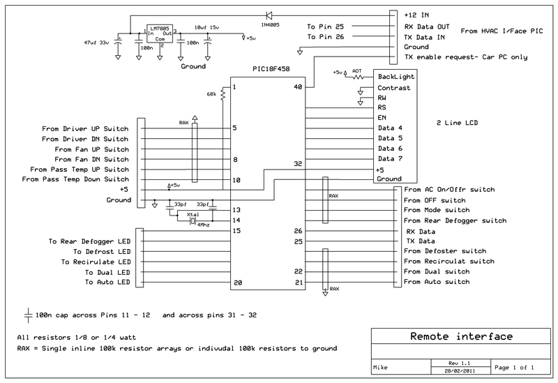
Remote interface micro.
Remote.pdf
Connections between the microprocessors and the data switch to share a common USB link
DataSwitch.pdf
Block wiring layout of the system in the vehicle.
Vehicle interface.pdf
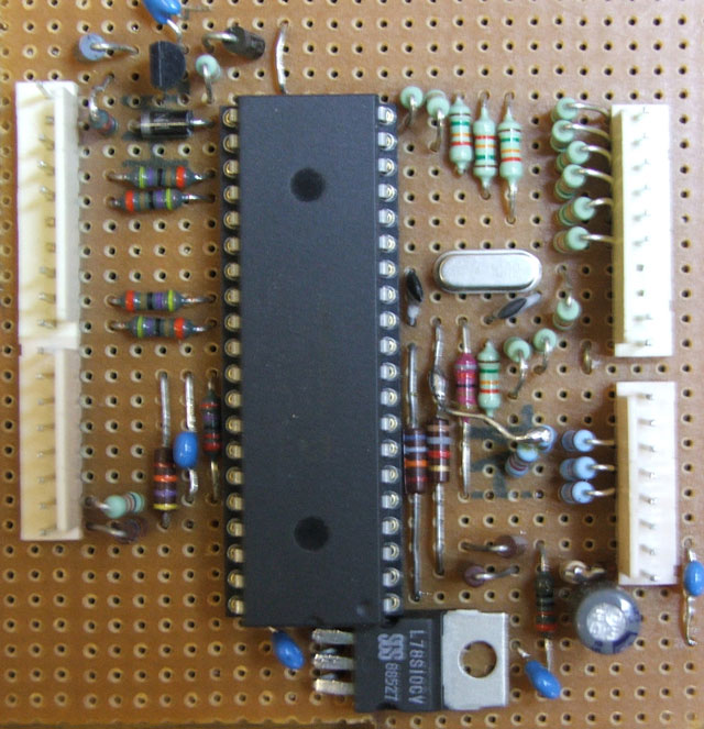
Pictures of the prototype PCBs that are currently installed in the vehicle.
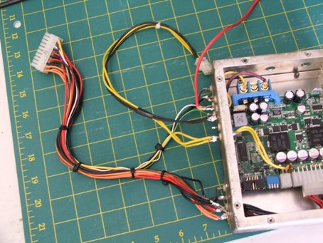
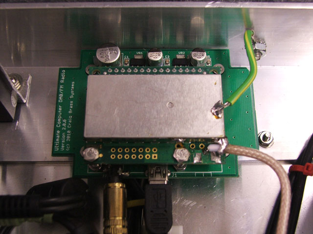
The HVAC (Climate Control) interface micro.
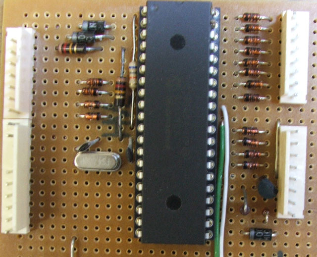
The Car Controls interface Micro.
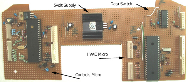
The Car controls and HVAC microprocessors along with the Data switch mounted in a case with the original HVAC/LCD board. This unit plugs into the system exactly as the original HVAC system did.
The wire connections going to the original PCB are simply soldered across the existing switches and LEDs. The only modifications to the original board are the removal of the two temperature rotary encoders.
These can be soldered back on, the wires removed and the original system can be reassembled and installed. Nothing is damaged or cut in this installation. The existing vehicle wiring and plugs are untouched. No dash modifications were made. The only mod was to the inside of the ashtray as a 4 port USB HUB in now mounted in there. The acc power socket in the tray is unchanged.
Forgot to highlight that fact that like most Screens this unit has its own 3 stage automatic brightness level. However that by itself was insufficient to bring the brightness down to unusable levels for night driving. The screen brightness now automatically changes with the Headlight switch and with dash illumination via a PWM signal to the Controls microprocessor interface. Both these signals wires are in the original head unit plug that now connects to the Controls micro.
Having the screen brightness follow the Head/Park light settings and vary with the dash brightness control further enhances the feeling of integration. Its just one more thing that is now fully automatic. The installation is at the point where anyone could get in the car and drive it without knowledge of the system.
Suspend to disk verses suspend to ram
Suspend to disk verses suspend to ram, like so many things in a Car-PC, it depends on hardware, how you want the system as a whole to perform and how you decide to power and wire it.
As I’m using a SSD, I have decided against suspend to disk for a number of reasons.
With my hardware it makes almost no difference – and I’m talking a second or two at most between loading the hibernate file and loading the operating system. This thing has a high benchmark and it shows in the disk read and seek load times. Once the Widow core is loaded and when most systems take quite some time to prepare the desktop (load user and background software/tasks) this is a 1.5 second affair. My main 4 drive raid system is left in the dust as the throughput of this drive is over twice the raid system which itself is over twice as fast as a single High quality drive in straight reads and seek.
For other owners who may be reading this – and I mean this nicely. If you disagree because your system is different, that’s fine, don’t make the mistake of assuming that mine is the same. Once bios initialisation is finished, Win 7-64 loads in 9.5 to 10 seconds flat. I mean the Frontend is running 2 seconds after that. It’s the 8 to 12 second wait before bios screen starts and then add 8 second bios load time that’s the killer.
Yes everything in the bios is optimised for the fastest boot. A dozen times over! Which is why I’m so interested in the links supplied.
Standby Power:
If you look at the vehicle wiring circuit, you will notice I have a small 14Ah (soon to be a flat profile 24Ah) sealed battery that powers the PC. I designed an automatic charge and isolate circuit for this system, also shown in the diagram. This setup will run the PC in suspend to ram for about 24 hours before it shuts it down. With this system there can “never” be a power drain issue with the Car battery, no matter what the PC does.
Resume from suspend to ram is 2 seconds, however almost a second of that is the M4-ATX IGN on sense delay. It is virtually an instant on system and you would never know that there is a PC running windows powering the system.
For me, that was one of the goals. I can be in and out of the car a dozen or more times a day and it just rocks, music is playing as I start the car and GPS is usually ready to navigate as I put it into gear (GPS ready time depends on how long I’m out of the car).
However the links and video posted really have my attention, as soon as I get a chance I intend reading up on this. So thanks again for the links.
The OSK: I had to input five different destinations today in a hurry, including way points. Now that I’m used to the key layout, it’s as easy and fast to use as my old standalone Garmin GPS, in fact it’s easier as my dedicated car GPS does not have a full page refined search lists display like Garmin MPC which is installed on the Car-PC.
iDrive Coding Started
Normally I dont post something new until I have a picture or two; however I just had to write about this new change.
Ok I know Ive harped on about implementing a sort of iDrive (see BMW) but part way through coding and I cannot believe how incredibly good this idea is with a Frontend and some apps.
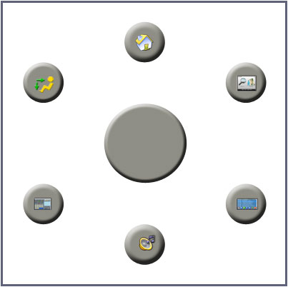
The system is based around controlling the Frontend or app with a Rotary encoder that has a built in momentary switch which is activated when the Encoder knob is pressed. Associated with this are six or so buttons surrounding the encoder with the lot placed in the centre console next too and slightly ahead of the driver/passenger with no reaching or looking required to use it.
Like Frontends, if you try to do too much with a good simple idea you turn it into a complicated mess. I know my Frontend looks simplistic and plain compared to others on here, however the purpose of a Menu system is to simplify not confuse. 99.9% of the time my Frontend is used solely when driving.
I designed it with big buttons and only a few on screen at any time. I dont have to be careful when pressing a button as you cant miss them and almost no text so nothing to read. Safety when driving and minimum distractions, did I mention safety.
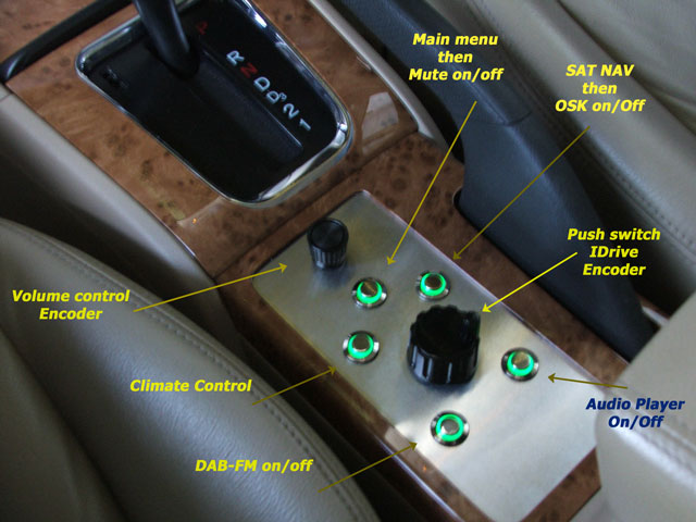
The way I will implement my “complete” system is with six buttons around the encoder which will select the main components used whilst driving – Climate Control, GPS, Radio, Audio Player, Mute and Menu.
These functions are already selectable from the steering wheel buttons so its already simple to use however once I started coding my version of an iDrive and saw what I could actually do with it I was hooked.
The part of the system I’m talking about is the Push-button Rotary encoder. It’s the heart of the system and a push of the encoder knob can either:
1. Bring up an on screen iDrive context sensitive menu with a graphical encoder knob in the centre of the menu. This graphic rotates to match and track the encoder knob and is used to either set the operation mode of the encoder within the current menu or application (which is remembered) or to select a quick action thats relevant to the current menu navigation screen and position.
2. Execute a menu or application item pointed to by either a graphical rotating encoder knob (which NOW replaces the Vehicle Graphic in the centre of the current menu screen if that option was set above in 1) or a highlighted menu or application item (like scrolling forward or back through a song list as the encoder knob is rotated and selecting a song by pushing the encoder knob.
Its a bit hard to describe but the power and ease of use is just awesome. If its coded correctly and kept simple, instead of making the system complex it actually simplifies it in an elegant and intuitive manner.
The complete FE system can be (if desired) completely controlled with just one knob the Encoder with its integrated button.
Now these functions are common; I and many others have them but usually hard coded into the apps or FE or selectable from a setup screen. Its the way its implemented and the way the Encoder and intergrated Encoder-button are programmed as a changing integrated object into the system that makes it so nice to use.
A small screen capture movie to come when I have created a few more graphics for my iDrive.
update:
I now have the basic system working and coded into the FE. Ive called mine FEiDrive.
The quick video shows the system being controlled via the Encoder and shaft push button only.
The final system will incorporate a layout like FIG1 which allows instant access to the most commonly used components while driving. These systems are already selectable from the Steering wheel controls; this layout brings everything to one central control position for passenger and driver and existing steering control is retained.
The Encoder in the video currently works like this:
When any menu is switched, the Encoder starts in Volume control mode.
One push of the Encoder (if enabled for that component) brings up a Graphic Knob to indicate the system is no longer in Volume mode. Rotating the Encoder selects the current scroll operation for the selected component, or in the case of say the Audio player, it will highlight the button associated with the Encoder scroll operation.
Double push of the Encode button brings up the FEiDrive select menu. From here you can.
1. Access Quick shortcuts to some menus.
2. Change the current scroll control for the current component.
3. Access single push actions for the current component operations.
4. Push the Encoder button without changing the selection and revert to Volume mode.
5. Double click to close the FEiDrive menu which takes you straight to the Home menu.
NOTES about the video: Quicktime Video.
The mouse pointer appears part way through, got no idea why, unless I bumped it.
Any flashing on the video is not seen on screen? Dont know or care why!
The encoder used in NOT the optical encoder used in the car, its a $2.50 mechanical encoder and the firmware in my control micro is not written for this type of encoder hence the less than smooth operation.
This system is running on a test bench, the Climate control micro is not connected, hence no climate control activity when buttons are pressed.
In case you are wondering the GPS map zooming in and out and all menu selections and screen changes are being controlled by the Encoder.
USB – resume.
USB ports, Software and Resume from suspend (to Ram in my case)
I found during the course of this project that any PC software that sends to a USB port as the OS is setting the hardware and software for suspend can (in my case usually does) cause the PC to not resume from suspend.
The familiar Windows screen Computer did not shutdown correctly is shown for a second as a cold boot takes place. In the case of my MB and M4ATX PSU combination the thing goes into a loop trying to start, but only with suspend to RAM though.
I made changes to the Interface Controls Micro to monitor the state of the Manual override on/off switch (IGN Line on the M4) and the ACC +12V. When ACC +12 is low (below 10v) or +12v on the M4 IGN line disappears, the Frontend stops all USB port activity. It also turns on the hardware Mute circuit at the input to the AMP. Once power is back or the PC resumes from suspend and the FE is running, an un-mute command is sent to the AMP mute control. Not even the faintest click can be heard with this Mute system.
Now to the interesting part, on the odd occasion the PC would not resume from suspend correctly.
Meters
Had some time yesterday to knock up a couple of graphic meters for my FE Voltage/Current monitor.
Monitoring:
1. Accessory voltage.
2. Aux battery voltage.
3. Aux battery charge current.
4. Main battery voltage.
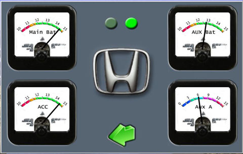
The Picture and video show it running on the test bench. I’m swinging the input voltage to one of the meters in the video. The meters are accurate and track (as visually possible) my digital meter.
Flashing screen LEDS indicate communication data with the Controls microprocessor.
BTW. Video quality is not that good.
UPDATE: I now have 8 meters available for basic PC and vehicle voltage/current monitoring.
When each meter is touched, a second (or third for a total of 12) meter can be selected or cycled through for each position. It keeps the screen uncluttered and easily readable at a glance.
I added a meter for reading the steering wheel pushbutton voltages, a meter for monitoring 12v supply to the HVAC CPU and a meter to read the Dash Light PWM signal that controls the Car PC screen brightness. These are handy to me for diagnostic and/or system interface mods further down the track.
I realised eventually that it only happened if I cleaned the LCD screen while in suspend. Turns out that this action of sending touch screen data to the USB port while in suspend causes the resume to fail. However my other USB devices and USB GPS receiver all send data to the USB ports while the PC is in suspend and cause NO issues. Go figure.
BTW, its not an OBVIOUS +5v standby, over current or other typical USB hardware problem. At least nothing that shows up with digital or analogue multimeters. Ill put a CRO on it when I pull the system out to relocate it for the final time, just in case there is some glitch thats not visible with standard equipment.
Either way Ill make a fix for it when I have the time, in the meantime no cleaning the screen when in suspend.
One Switch
I came up with a great solution for ON-Off, Suspend and shutdown options using just one switch, most likely been done before but something to keep in mind when designing a system.
With most PSU designs there is an input line to the PSU to turn the PSU-PC on and off. In the M4 it’s called the Ign line. A voltage on this line turns the PSU on and, it in turn, sends a start pulse to the MB on/off connector, just as you would do when turning the power on and pressing the on/off button on a home PC.
Removing this voltage causes another pulse to be sent to the MB on/off connector to shut the PC down into whatever state is set in the Bios and Operating system for Power button action, following this, the PSU usually goes into some low power state and waits for the Ign (on/off) line signal to go high.
In my case I have the PC set to suspend to Ram (STR) and because I sometimes don’t drive for a few days at a time I have a button on the FE menu that allows me to shut the PC down, as opposed to automatically going into STR when the vehicle is turned off. I was looking for a way to remove this menu item.
I have a locking push button (locks on or off as opposed to momentary) between the Accessory line from the vehicle and the ign (on/off) line to the M4. This gives me the option of not starting the PC when the vehicle is turned on, or to STR without turning the Ignition (motor) off. Normally the switch is left ON for automatic start/suspend operation of the Car PC.
I realised that it’s a simple matter to monitor the voltage on the switch AND the Vehicle ignition line. I already monitor the line coming from the switch to the PSU. I did this to stop the FE software sending data to USB ports as the PC is going into STR. This solved a strange resume from STR problem I was having.
By monitoring the Ignition ON voltage from the vehicle Ignition switch (as opposed to the accessory voltage position) I have now incorporated simple logic into the FE to Shutdown the PC (not STR) when the On/Off switch feeding the M4 Ign line is switched off while the vehicle Ignition is switched ON (all dash gauges and dash indicator lights on and/or motor running).
If the vehicle ignition switch is in the “Accessory position” and the M4 ign-line switch is turned off or the vehicle ignition is switched off completely the PC automatically goes into STR as before.
Simple, elegant and no menu to select or screen input needed.
the control
Finally, I have the controls, layout and operational interface set (not in stone but close).
I was planning to wait a while before adding the iDrive style interface hardware, but a sudden realisation that I could mount a panel in place of the drinks holder in the centre console bought that forward. I had wrongly assumed (in the past) that I would have to remove the auto opening door from the drinks holder, however a closer look revealed the door and pocket came away as one unit.
It was then a simple task to add a fascia panel without any modifications to the existing console.
So after 5 hours of work, here is a quick picture, please excuse the blur, the flash washed out everything if used so dim lights and hand movement is the result.
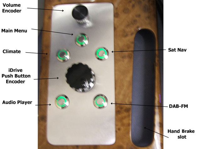
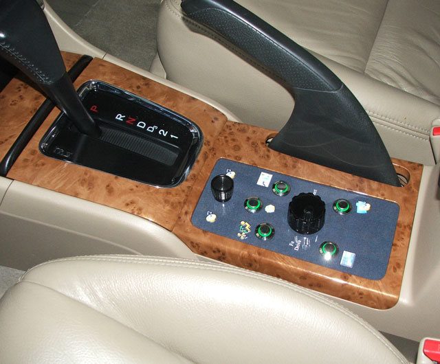
This panel sits between the Centre arm rest and the Gear shift lever and is in a perfect position to comfortably use without having to reach. The long opening is for the Hand Brake lever.
The buttons have inbuilt LEDs that illuminate the outer ring around the button. Looks great at night and I have taken the PWM signal from the dash controller and used it to control the brightness and illumination of these buttons.
I had earlier combined the Volume and iDrive encoders but decided that a separate volume knob was indispensable. This arrangement has turned out better that I had hoped for. Controlling the FE with this is an absolute joy.
I can at last get around to making the cover panels for the screen and controls.
As a side note- Found a way to detect when the PC is going into standby, but more importantly detect it coming out of suspend/standby. Occasionally I would have to move the volume knob to un-mute the system on resume from STR, now it works faultlessly.
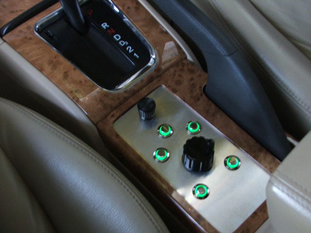
First try of the centre console FeDrive controls in the car, in one word, fantastic
Everything works perfectly and I added a few new items to one of the setup screen.
1. FeDrive Encoder step rate.
2. Menu Clicks On/Off.
3. FeDrive Clicks on rotate – On/Off.
4. FeDrive Buttons Voice announcements On/Off.
I also added Dual functionally to the buttons.
If Menu button pressed and already at Main Menu then toggle Mute / Un-mute. (Hardware mute at Amplifier input.)
If GPS button pressed and GPS is on screen then toggle the OSK on/off – that change just rocks!
If Climate button pressed and Climate is on Screen then toggle FeDrive select menu on/off.
This allows selection of any HVAC function from the FeDrive encoder.
I thought my Car-PC with integrated Steering buttons, Volume knob and Screen brightness automatically controlled by the vehicle lightning system was feeling pretty OEM integrated.
This new system has taken that to a whole new level of feel and integration, to the point where the original OEM system now feels like the add-on. Im just blown away with the simplicity of use.
I have a way of doing backlit Icons next to each button and will incorporate that into the insert panel when I decide on the final colour, dont know if I should go with the wood grain or dark charcoal finish of the upper dash, guess it depends on what colour I do the Screen surround panel.
Still to do:
1. Convert the FeDrive encoder to torque/indent feedback.
2. Redo and relocate the CarPC enclosure to a different location in the trunk and incorporate flow through ventilation to the rear breather vents. Amazing how a boot full of air can slowly heat up after 3 or 4 hours driving on a hot day – PC is still within limits but I like things running luke warm to cold. Put the rear centre arm rest down and open a small panel that allows a tiny amount of cool cabin air into the trunk and it then runs cold all day in summer heat.
Encoder’s can have a step rate of a few pulses per 360 deg of rotation to thousands of pulses. The Mechanical encoder I use for volume control has 16 and the optical encoder for the FEDrive has 128. Depending on the application, some mechanical encoders can be a dog to control without correct denounce software “and” hardware.
Anyway, after a few days of testing my new FEDrive system, the need for rotational speed sensing “auto variable encoder step-rate” became obvious.
Two problems arose; for example scrolling song lists can be too fast to read at times. Easy solution is to turn the encoder slowly, however, if a Menu is being scrolled then it takes a bit of concentration to scroll slowly, and that is undesirable when driving.
To alleviate the problems above, I had an automatic two speed scroll rate implemented for Menus and lists; this was fine until it came time to “press” the encoder knob to select a song from a song list. Song lists are scrolled at a faster speed and in doing so it became very hard to just “casually” press the Encoder knob without moving it to another track, it was also difficult for a passenger to do this with any car movement. Worked ok on the bench though but then it wasn’t moving!
Anyway, after a lot of trial and error I managed to implement continuously variable encoder rate relative to rotation speed. I included two adjustment sliders in the Encoder setup menu to tailor this to almost any encoder pulse rate.
Now, when you slow the encoder, or stop turning the encoder in order to select the desired song, any slight movement of the encoder is rejected because the required number of Encoder pulses to trigger a valid step rapidly increases with slowing speed.
It really works well, scroll speed moves up or down smoothly with varying encoder rotation speeds and pushing the encoder as carelessly as you like causes no jump from the highlighted track.
The next task is to redo the Hardware USB controlled Volume and Mute unit that sits at the input to the Amplifier. I need to get positional information back from this control in order to implement automatic speed and noise variable sound level for the FE.
The overall impression of the Car-PC is that it now feels like it was meant to be part of the vehicle. There was a time when I begin to question whether it was worth the effort, expense, and monumental amount of time I was/am putting in to this and there were so many silly things that I never thought of that kept cropping up, but dam its working beautifully now.
My enthusiasm for doing the hard part which I hate has returned. That is: Running new cables and adding a few extra, relocating and moving the PC into a new case, and finally, making it look nice.
Oh and making a few videos.
M4-atx
M4-ATX and an attempt to find/mod a supply that generates less or no spurious noise (interference).
Since I’m rebuilding the case and PC layout I decided to take another look at the M4 and locate an audio noise that is “absolutely” coming from the M4, however due to other issues I have with the firmware of this device I decided to look at an alternative first.
During the course of my initial tests, when trying to make the M4-ATX usable near a GPS and DAB radio in weak signal locations, I tried a small low cost supply from Jaycar.
This is a 205 watt unit, it’s nicely made and it did indeed produce very little RF interference.
However it had at that time two limitations:
1. The 12v input is not regulated or boosted – and is a major reason for its low noise.
2. It has no start-up or shutdown controller.
The second problem is not really a problem as the M4-ATX PC interface and shutdown controller sucks!
It will take me all of a day to make a microprocessor interface with voltage monitoring and controller settings available in a small windows application that blows the M4 dumbness out of the water.
The first problem allowed me to find a way to regulate the +12v supply using some form of linear regulation – NO switching regulator to generate noise. I will not be boosting the 12v rail as I run the PC from a small aux battery AND boosting the rail requires some form of switching convertor.
Yes I know +5v and +3.3v rails use a switching regulator, however the voltage is low and the power is low in relative terms, it’s that switching +12v @10A (or more) regulator/booster that is the real noise maker.
There are problems using a standard linear regulator due to the voltage drop across the device when the input voltage approaches or drops below the design regulated output voltage. And NO, I’m not interested in some exotic circuit that you may have to overcome that.
I had an idea for a simple low cost (some would call it crude) system to keep the voltage at around +12v +- 5% from an input of 11.5v to 15v. However I wondered just what tolerance my MB would take before it spat the dummy (Signalled power good failure or just stopped).
The CPU and most circuitry in a modern MB are 5v or below. I assume that the input to the switching regulators for most of these devices is usually the +12v supply, therefore I could see no reason why it could not run at much lower supply. Searching the NET was a waste of time with usual folk law and totally dumb/wrong information trotted out as fact.
The test on my MB was surprising, I don’t know how low I can take the +12V rail but I decided to stop at +8.4 volts. The PC boots and runs faultlessly at that voltage.
NOTE: I should point out that there could be a “Major problem” in taking the 12v rail low. The CPU and other circuitry can be drawing high currents and the switching regulators for these devices will be drawing more and more current as the input voltage drops. It’s possible to go outside the design limitations of the MB and damage it.
I reasoned that if I kept the +12v to a max of +12.4v and I feel I could safely run the MB down to 11v. Actually I think it would be fine down to 10.5 volts.
This relaxed the very fine regulation requirements and allowed me to try an idea for a controller consisting of 3 x 30A diodes in series, each shunted by a power MOSFET. The FET’s are controlled by a small voltage monitor and switched progressively on or off as the input voltage changes.
Each diode has a forward drop of almost 800mv for a total drop of 2.4 volts in three 800mv steps.
With this circuit the output voltage swings between 11.7 and 12.4 as the input voltage varies from 11.8 to 15v at currents from 2A to 20A.
At an input voltage of 10.9v the output is 10.7v.
This circuit causes absolutely no noise, the total dissipation at 15v input and 10A is around 24 watts, at the normal running current of 3.3A its 8 watts. This is with an input of 15V which it will never see due to wiring length and the Vehicle regulator.
At a nominal 13.6V input at 10A the dissipation is around 16 watts. At 12v @ 3.3A output for 13.6v input (PC runs at that all day) power dissipation in the circuit is around 5 Watts.
This is a very simple low cost circuit and should be almost indestructible. Combined with the Jaycar PSU, it results in a complete absence of interference in the Audio, FM, DAB and GPS spectrums.
It has been running the Car PC all day at 14v input and is cold to touch.
Goodbye M4-ATX.
I have been away for a while with health problems (ongoing) but Im just getting back to the install now.
Before stopping work on the install I was looking at different power supplies in a bid to reduce the last of the noise from the system and to trace a strange problem where the PC would randomly fail to resume from STR, in doing so it would go into a loop of continually trying to boot and instantly failing (but only when trying to resume from STR Hibernate is fine). Power had to be removed from the PSU/MB to resolve the problem.
The loop problem turned out to be a Mother Board design problem as other MBs dont have this behaviour and the behaviour follows the MB.
The random failure to resume from STR turns out to be a complex interaction between the MB and the PSU, in some installations it may never show up, but if you get the right conditions of input voltage change, noise when cranking, direction of wind and moon cycle, it can happen. Other PSUs caused this to happen quite frequently, the M4 was better than other supplies I tried.
It really is a chicken and Egg syndrome as the failure is caused by either the PSU thinking there is a problem and dropping +5v Standby OR the MB is (for some reason) signalling a power good fault and resetting the PSU and therefore dropping +5v Standby. Any interruption to +5v standby voltage will cause a failure to resume from STR.
With a MB that does not go into a start-up loop there is no problem, just a delayed cold boot.
During the course of these tests I came to the conclusion that the M4-ATX (when placed in an RF shielded enclosure with feed through caps on all leads) works really well and is causing no problems.
One problem with a trunk install can be heat. The existing system draws only 36 Watts, however after 3 hours of driving on a hot day the air inside the boot is gradually heated by the system and although the temps are within design limits there would be a real problem with a trunk full of luggage on a hot day.
To try and overcome these problems I decided to redesign the case and rebuild the PC for the third time, and as it turned out, the final time. I wanted full control of layout, separation of modules and full control over a common ground plane without compromising for lack of space.
The MB was updated with a new model from Gigabyte. This new MB with the same processor and ram draws just 24 watts when running (the older model was 36 watts) Peak start-up current is halved from 8A to 4A and the system heat-sink is now a much larger unit.
This complete system including 8 LCD and all devices powered draws a total of 35 watts from the supply.
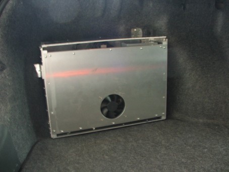
These pictures show the case on the work bench with the Lid open and closed.
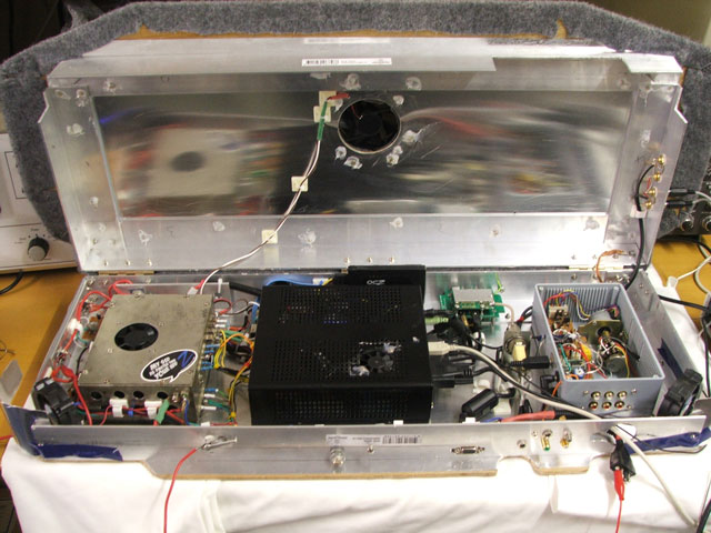
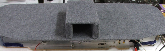
The case is made from thin sheet aluminium (low cost) and aluminium angle bracket. Both items were available at the local hardware. The thin aluminium sheet is glued to a ply top and bottom panel. The angle bracket is cut and screwed to the ply top and bottom panels.
The lid is secured by three hinges and is electrically bonded with a thick flexible copper strap.
When the lid closes, the angle brackets snugly overlap with the top lid brackets resting on 3 large limit screws. This makes a very strong light case that, when mounted in the trunk, supports any weight of luggage that is placed/thrown on top.
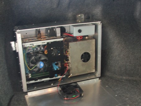
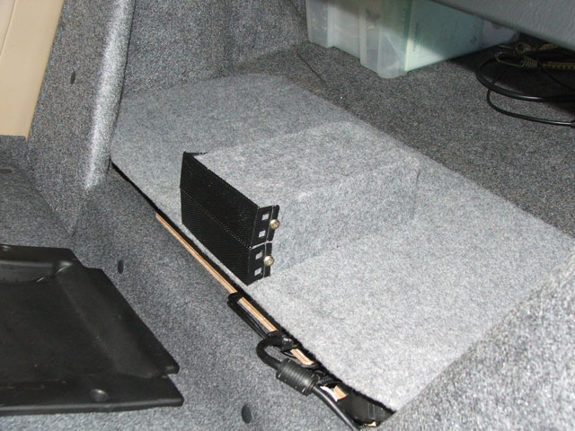
Case with back seat down.
The forward facing vent has a filter and fan which cannot be blocked by anything thrown into the trunk.
Case open with back seat down.
Location of vent with arm rest.
From the Trunk.
Picture of the earth strap added to the DAB-FM radio module that cured the last of the noise that I had been trying to eliminate. The design of this DAB-FM module does not correctly ground the RF shield, adding the thick green earth cable directly to the case removed all noise and improved the reception so much that this receiver now outperforms a high quality dedicated car receiver. This connection is an RF ground not a DC ground; it must be “short” and thick. Do not confuse the effect of this earthing with audio or DC ground loop earthing principles.
I added an Aerpro amplified roof mounted AM-FM DAB antenna, this unit has 3 lead connections, FM-AM coax, DAB coax and a separate power lead. The aerial input to the receiver has to be switched when changing from DAB to FM and this is done automatically by my DAB-FM radio application through the FE software. I used this high quality RF relay as I’m in a fringe area for digital reception and wanted as low a loss connection as possible.
This aerial is fantastic, all DAB stations received, even under a 6 x 6 meter steel carport behind a steel panel lift door. Mounting the aerial through the rear car roof and getting the leads back to the receiver turned out to be one of the easiest mods I have made to this vehicle.
Picture of the Aerial changeover relay; it’s taken from an old mobile radio I junked.
It’s the yellow block thing mounted to a bracket.
The Fe-Drive and control panel with icons and labels. It’s hard to get a picture because of reflections from the finish when using a flash.
Now all I have left to finish is the centre dash panel. This is a picture of the prototype centre dash backing panel in black, once again the screen is washed out because of the angle and camera flash.
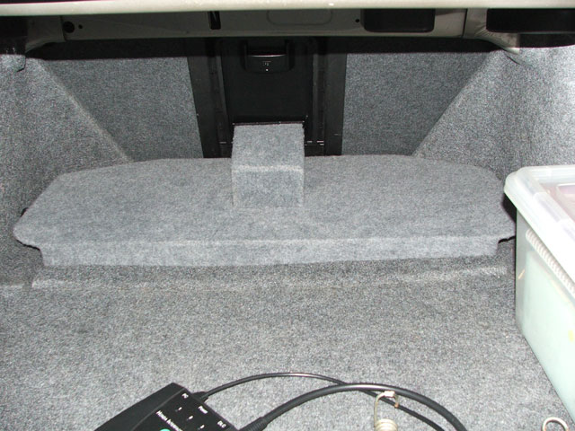
I have gone from a small system behind the dash (the first build) to a larger case mounted in the boot and now to this very large case mounted in the boot in a recess in the floor behind the back seat. This is a fabulous location in this CAR. The new case draws air through the rear seat centre arm rest and exhausts air into the boot spare tire well. It runs as cold as, even on the hottest of days.
The larger case is a joy to work on and make changes to hardware. Simply lower the back seat and lift the lid, no screws to undo, no reaching into inaccessible places. Most connections are too sockets mounted along the front of the case and it literally takes under 2 minutes to remove the PC from the car and have it running on the bench.
The boot can be filled with luggage chucked in anywhere without any concern about blocking vents or throwing anything on top of the PC.
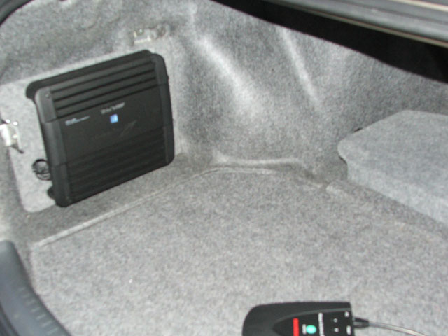
Almost forgot to include a picture of the Alpine amplifier mounted where the old PC case was located.
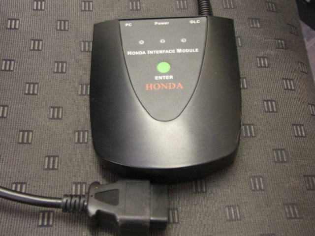
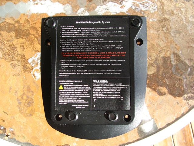
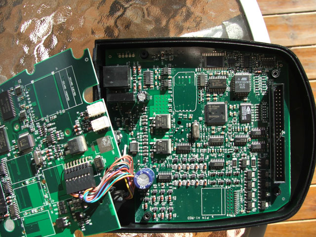
Off track but anyone interested in the OBD-II HONDA Interface module for the Honda HDS might find this interesting. HDS (Honda & Acura Diagnostic System). HONDA/ACURA from year 1992 to 2009. The HIM comes with Honda diagnostic software for a PC.
The software is designed for a touch-screen and includes an OSK (on screen keyboard). I have tried it on Win-XP to W7 32 bit and 64 bit. I run 1024 x 640 on my 8 widescreen and Im not sure how it goes on smaller resolution.
The HIM device was only available to the HONDA dealers and is the only OBD-II unit that can show all of the Honda propriety system information. Even the (expensive) Auto Enginuity OBD-II ScanTool with the HONDA add on software module cannot do the functions, Vehicle system setup-up and component diagnostics of the Honda unit.
Its been said that these units (this one from Hong Kong ) are a knockoff of the original RERADYNE unit however I have my doubts, especially when you see whats in these, how well they are made and the fact that internal Firmware would have to be reversed engineered to get these units to function.
The Honda device costs over a thousand dollars to purchase from official outlets, however this unit cost me $168 delivered to my door (price is now around $180 delivered). It payed for itself the first time I had a problem from an apparent electrical glitch that had caused an ABS sensor to go out of calibration. The Honda workshop manuals (which use the HIM in most of the repair and testing procedures) and the HIM with the supplied Honda software pointed to that as the most likely cause of the problem. There were special instructions to recalibrate the sensor using the HIM which worked as described. Without the HIM the dealer cost would have started at around $160 and gone up from there.
The information available on all vehicle systems and the diagnostics you can carry out is amazing, however if these advanced features are used without a full understanding of what you are doing you can easily cause damage to the vehicle.
IMHO this is the real Honda unit, I purchased another recently in case one fails or they become imposable to get. When you consider how complex a modern vehicle has become and the strange but simple problems you can encounter as they age, any of which can stop the car from running, its becomes cheap insurance, especially if youre a Car DIY type and plan on keeping the vehicle for a long time.
The second unit (not shown) is a slightly later REV and has a single board with larger SM Micros. Both work exactly as the Honda Workshop manuals state.
The seccond unit.